← Back to Projects
Master Project · SIM-01-FEA

Advanced Simulation & FEA

ANSYS · MATLAB · InterShear · In-Plane Decoupling

Download Full Report
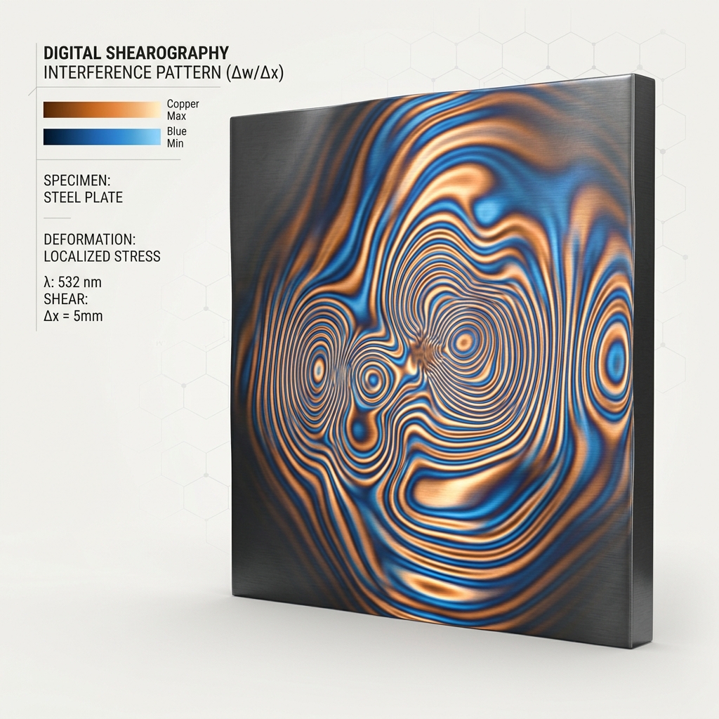
Digital Shearography Interference Pattern
01 / THEORY
The Challenge
Shearography is mainly for out-of-plane measurement. The core goal is to achieve in-plane detection.
Adaptation
02 / SIMULATION
Design & FEA
Specimen designed and analyzed in ANSYS to generate controlled in-plane structural deformation.
360 N Loading
03 / OPTICAL
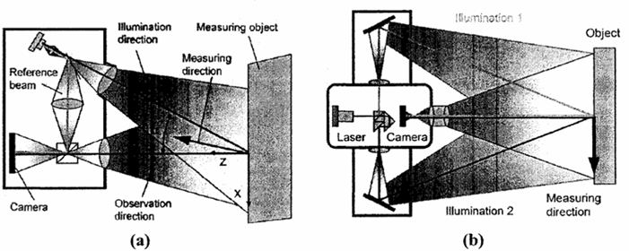
Dual-Beam Setup
Optical setup modified with 45° illumination and phase subtraction to isolate in-plane movement.
InterShear Pipeline
04 / RESULT
Differentiation
Successfully detected and differentiated in-plane deformation caused by weld geometric changes.
2-Edge vs 3-Edge
Overcoming OOP
Limitations
Structural Rigidity
& Deformation
Phase Subtraction
Decoupling
In-Plane Deformation
Achieved
Explore the methodology
Project Context
The Challenge

Adapting Out-of-Plane Tech for In-Plane

Digital Shearography is traditionally designed to measure out-of-plane deformation. The challenge was to develop a simulation framework that adapts this original setup to accurately capture and evaluate early-stage in-plane deformation.

The Solution

Simulation-Driven Geometric Evaluation

Using a combined pipeline of ANSYS, InterShear, and MATLAB, we can simulate fringe interference. By differentiating between two models with distinct geometric changes, we can evaluate structural performance and drive data-backed redesign decisions.

The Key Equation: Optical Decoupling

By illuminating from two symmetric angles (+θ and −θ at 45°), two phase distributions are generated. Their subtraction eliminates the out-of-plane term and doubles in-plane sensitivity. Click any annotation to learn more.
N+θ = (δx / λ) · [ (∂u/∂x) sin(θ) + (∂w/∂x)(1 + cos(θ)) ]
N−θ = (δx / λ) · [ −(∂u/∂x) sin(θ) + (∂w/∂x)(1 + cos(θ)) ]
Ndiff = N+θ − N−θ = [ 2δx sin(45°) / λ ] · (∂u/∂x)
Out-of-Plane Coupling
ELIMINATED
In-Plane Sensitivity
×2 DOUBLED
Illumination Angle
θ = 45°
Shearography Setup
N+θ
Positive-angle phase map
Fringe order from the +45° illumination beam. Contains both in-plane (∂u/∂x) and out-of-plane (∂w/∂x) contributions.
→ See FEA Setup
δx / λ
Shear-to-wavelength ratio
Governs fringe sensitivity. Larger shear distance δx or shorter wavelength λ both increase fringe count per unit strain.
→ See Optical Params
Ndiff
Differential phase map (result)
The key output: pure in-plane strain derivative ∂u/∂x, decoupled from bending noise. This is the innovation.
→ See Results

Research Hierarchy

LEVEL 01
Step 1 — The Setup
Adapting Digital Shearography for in-plane deformation
Unlocked

The first step is establishing the baseline design. We take the original optical setup of digital shearography, which is inherently built for out-of-plane measurement, and adapt the simulation framework to isolate in-plane deformation.

Foundation: Preparing the base virtual environment to accurately capture strain fields before introducing geometric variables.
Theoretical Setup Fringe Pattern
unlocks →
unlocks →
Author
Darshit A. Solanki
Supervisor
Prof. Dr.-Ing. Michael Schuth
Institution
Trier University of Applied Sciences
Duration
Nov 2025 – Jul 2026
Tools
ANSYS 2025 · MATLAB · InterShear
Reverse Engineering & Metrology
Next Case Study

Reverse Engineering & Metrology

Explore Project